Filter & Amp Sections
Filter Section
Within each Machine that uses the standard signal chain, the sound source is always routed through a similar Filter section, available on Tab 3. Each Filter section then goes to an Amp section before reaching the Mixer.
The Filter tab has 3 pages of controls. When the tab header shows small bar icons, click the corresponding button below to jump between pages.
Main screen of the Filter section
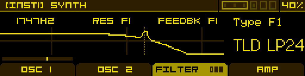
Page 1
| Filter 1 Frequency | Filter 1 Resonance | (Filter Morph) -or- (Filter Gain) | Filter 1 Type |
| Cutoff frequency of the filter. | Resonance amount of the filter. | Morph between the filter types, from Low-pass to Notch to High-pass. Only available when Filter 1 Type is set to SVF 12. -or- EQ gain. Only available when Filter 1 Type is set to BELL EQ. | Selects a filter model and slope. See the Filter types reference below for details. This parameter cannot be modulated. |
Page 2
Same as page 1, but for Filter 2. Available only when Routing on page 3 is set to anything other than Single.
Page 3 — routing
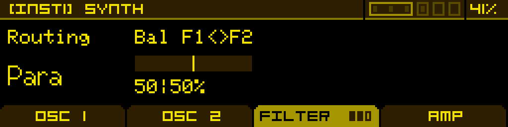
| Routing | Balance F1/F2 | - | - |
| Filter routing configuration: - Single — only Filter 1 is enabled. - Serial — Filter 1's output feeds Filter 2. - Para — both filters run in parallel on the same input. - Split — the Machine's two sources are sent independently into Filter 1 and Filter 2 (see Input reference below). | Mix between the two filter outputs. Fully clockwise = only Filter 2; fully counter-clockwise = only Filter 1. | - | - |
Filter routing diagrams
Single filter
flowchart LR
    I1["INPUT 1"]
    I2["INPUT 2"]
    SUM(("+"))
    F1["FILTER 1"]
    OUT["TO DRIVE & AMP"]

    I1 --> SUM
    I2 --> SUM
    SUM --> F1
    F1 --> OUT

    classDef in fill:#06b6d4,stroke:#22d3ee,color:#fff,stroke-width:2px
    classDef sum fill:#1f2937,stroke:#9ca3af,color:#fff
    classDef filter fill:#65a30d,stroke:#a3e635,color:#fff,stroke-width:2px
    classDef mixer fill:#9333ea,stroke:#c084fc,color:#fff,stroke-width:2px

    class I1,I2 in
    class SUM sum
    class F1 filter
    class OUT mixer
Serial filters
flowchart LR
    I1["INPUT 1"]
    I2["INPUT 2"]
    SUM(("+"))
    F1["FILTER 1"]
    F2["FILTER 2"]
    OUT["TO DRIVE & AMP"]

    I1 --> SUM
    I2 --> SUM
    SUM --> F1
    F1 --> F2
    F2 --> OUT

    classDef in fill:#06b6d4,stroke:#22d3ee,color:#fff,stroke-width:2px
    classDef sum fill:#1f2937,stroke:#9ca3af,color:#fff
    classDef filter fill:#65a30d,stroke:#a3e635,color:#fff,stroke-width:2px
    classDef mixer fill:#9333ea,stroke:#c084fc,color:#fff,stroke-width:2px

    class I1,I2 in
    class SUM sum
    class F1,F2 filter
    class OUT mixer
Parallel filters
flowchart LR
    I1["INPUT 1"]
    I2["INPUT 2"]
    SUM(("+"))
    F1["FILTER 1"]
    F2["FILTER 2"]
    MIX(("MIX"))
    OUT["TO DRIVE & AMP"]

    I1 --> SUM
    I2 --> SUM
    SUM --> F1
    SUM --> F2
    F1 --> MIX
    F2 --> MIX
    MIX --> OUT

    classDef in fill:#06b6d4,stroke:#22d3ee,color:#fff,stroke-width:2px
    classDef sum fill:#1f2937,stroke:#9ca3af,color:#fff
    classDef filter fill:#65a30d,stroke:#a3e635,color:#fff,stroke-width:2px
    classDef mixer fill:#9333ea,stroke:#c084fc,color:#fff,stroke-width:2px

    class I1,I2 in
    class SUM,MIX sum
    class F1,F2 filter
    class OUT mixer
Split filters
flowchart LR
    I1["INPUT 1"]
    I2["INPUT 2"]
    F1["FILTER 1"]
    F2["FILTER 2"]
    MIX(("MIX"))
    OUT["TO DRIVE & AMP"]

    I1 --> F1
    I2 --> F2
    F1 --> MIX
    F2 --> MIX
    MIX --> OUT

    classDef in fill:#06b6d4,stroke:#22d3ee,color:#fff,stroke-width:2px
    classDef sum fill:#1f2937,stroke:#9ca3af,color:#fff
    classDef filter fill:#65a30d,stroke:#a3e635,color:#fff,stroke-width:2px
    classDef mixer fill:#9333ea,stroke:#c084fc,color:#fff,stroke-width:2px

    class I1,I2 in
    class MIX sum
    class F1,F2 filter
    class OUT mixer
Input reference (per machine type, in Split routing)
| Machine | Input 1 | Input 2 |
| Synthesizer | Oscillator 1 | Oscillator 2 |
| Sample Player | Sample | — |
| Granular | Granular cloud | — |
The Resonator, Simple Oscillator and Drum Synth Machines do not use this unified Filter section. The Resonator and Drum Synth each have their own filter stage built into the Machine; the Simple Oscillator skips every downstream stage and goes straight to the Mixer.
Filter types reference
The filter slot offers 9 filter models organised into 5 families. Each model can come in several variants (slope, type) — pick the one that matches the slope and character you need.
Filter families
| Family | Inspired by | Character |
| SVF | State Variable Filter (Oberheim SEM) | Smooth, neutral, musical. The morphing variant SVF 12 continuously sweeps from LP to Notch to HP via Knob 3. |
| TLD (Transistor Ladder) | Moog ladder | Warm, fat, classic analog low-end. The widest selection of slopes (6, 12, 18, 24 dB/oct) and types (LP, BP, HP, Notch). |
| K35 (Korg 35) | Korg MS-10 / MS-20 (early) | Aggressive, slightly nasal, well-known for cutting leads. |
| OTA | Korg MS-20 (later, OTA-based) | Distinctive bite, vocal resonance peak, edges into self-oscillation. |
| STP (Steiner-Parker) | Steiner-Parker Synthacon | Punchy and articulate, with a distinct response curve compared to ladder filters. |
| DLD (Diode Ladder) | Roland TB-303 | Squelchy, acidic 24 dB/oct low-pass with strong resonance. |
| COMB | — | Comb filter for hollowed-out, metallic and "whoosh" textures. + and − variants invert the feedback polarity. |
| FORMANT | Vocal tract | Vowel filter — Knob 1 morphs through A → E → I → O → U. |
| BELL EQ | Parametric EQ | Single-band bell. Knob 2 sets the bandwidth, Knob 3 sets the gain. |
Available variants
| Family | Variants |
| Off | Filter is bypassed. |
| SVF | SVF 12 (morphing LP/Notch/HP, 12 dB/oct), SVF BP12 (fixed band-pass, 12 dB/oct). |
| TLD — low-pass | TLD LP6, TLD LP12, TLD LP18, TLD LP24. |
| TLD — band-pass | TLD BP12, TLD BP24. |
| TLD — high-pass | TLD HP6, TLD HP12, TLD HP18, TLD HP24. |
| TLD — notch | TLD N12, TLD N24. |
| K35 | K35 LP12, K35 HP6. |
| OTA | OTA LP12, OTA LP24, OTA HP12, OTA HP24. |
| STP | STP LP12, STP BP12, STP HP12. |
| DLD | DLD LP24. |
| COMB | COMB+, COMB−. |
| FORMANT | FORMANT. |
| BELL EQ | BELL EQ. |
Tip: when picking a slope, remember that lower slopes (6 dB/oct) leave more harmonics through and sound airier, while steeper slopes (24 dB/oct) cut more aggressively. The TLD family is the only one that exposes every slope from 6 to 24 dB/oct in LP and HP, which makes it the most flexible workhorse of the bunch.