Synthesis Machines
Synthesizer
General information
This Machine features 2 identical oscillators, each able to run any of 18 different algorithms (the model). Each oscillator can be tuned, transposed and have its own model.
flowchart LR
    OSC1["OSC 1"]
    OSC2["OSC 2"]
    FILT["2 MULTIMODE FILTERS
WITH DIFFERENT ROUTINGS"]
    DRV["DRIVE"]
    DCA1["DCA 1"]
    DCA2["DCA 2"]
    OUT["TO MIXER"]
    FLTENV["FLT ENV"]
    AMPENV["AMP ENV"]

    OSC1 --> FILT
    OSC2 --> FILT
    FILT --> DRV
    DRV --> DCA1
    DCA1 --> DCA2
    DCA2 --> OUT
    FLTENV -.->|"cutoff"| FILT
    AMPENV -.->|"VCA"| DCA2

    classDef osc fill:#06b6d4,stroke:#22d3ee,color:#fff,stroke-width:2px
    classDef filter fill:#65a30d,stroke:#a3e635,color:#fff,stroke-width:2px
    classDef drive fill:#eab308,stroke:#facc15,color:#000,stroke-width:2px
    classDef dca fill:#ec4899,stroke:#f472b6,color:#fff,stroke-width:2px
    classDef mixer fill:#9333ea,stroke:#c084fc,color:#fff,stroke-width:2px
    classDef env fill:#831843,stroke:#f472b6,color:#fff,stroke-width:2px

    class OSC1,OSC2 osc
    class FILT filter
    class DRV drive
    class DCA1,DCA2 dca
    class OUT mixer
    class FLTENV,AMPENV env
The oscillators go into a Filter section, then a Drive section and finally an Amp section before going to the Mixer.
Main screen of the Synthesizer
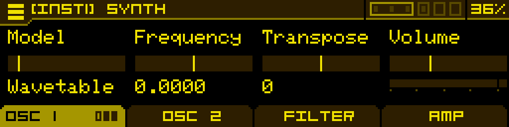
When opening the Synthesizer Machine you will land on page 1 of tab 1. Use the first 2 tabs to configure oscillator 1 and 2 respectively. Use Tab 3 to configure the Filter section and Tab 4 to configure the Amp section.
The oscillator tabs (Tab 1 and Tab 2) will have a number of pages containing different controls depending on the selected model. When a Tab header displays small bar icons, click its corresponding button underneath to jump between its pages.
When you adjust a parameter on one of the pages, a wave display is briefly shown to reflect the changes on the output wave. Click Button 4 while the wave display is shown to lock it on. Click Button 4 again to unlock the display.
The first page of an oscillator tab is always the same:
| Model | Frequency | Transpose | Volume |
| Select the synthesis type used in the oscillator | Fine-tune the oscillator. This can be used to achieve beating-effects by having the two oscillators slightly out of tune with each other | Tune the oscillator by one semitone increments. This can be used to have the Machine play a paraphonic interval, or use one oscillator as a sub | Adjust the volume at which the oscillator is sent down the signal path (to the Filter section, or directly to the Amp section if all filters are turned off). 100% is unity gain, but it can go up to 200% if you want to overdrive the Filters, Amps or even the final DAC. |
Wavetable model
A wavetable oscillator with deep wave-reshaping capabilities. The Wavetable model has 3 pages. Page 1 is the same as mentioned earlier.
On any page, the encoder is used to select wavetables in the current folder. Click the encoder, then "Load wavetable" to load other wavetable folders.
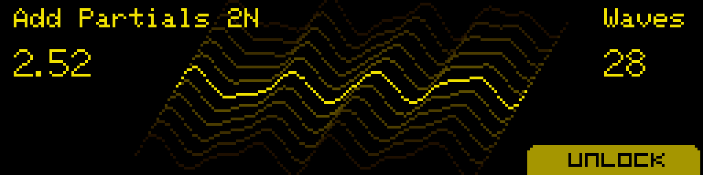
When turning the encoder (or the Position knob), a dedicated display will pop-up, showing the name of the wavetable, the position you're in, the number of waves in the wavetable and a wave display. This screen will stick for a couple of seconds, but you can lock it if you press button 4, labeled "Lock". Use knobs 2 and 3 to adjust the X and Y axis of the wave display to your liking.
The Position parameter ranges from 1 to N (with N = number of waves in the wavetable). Intermediate (non-integer) values are interpolated between the previous and next waves when the Transition is in Morph mode.
Wavetable libraries
There are 65 factory wavetables, licensed with Galbanum (https://www.galbanum.com/) derived from their "Architecture Waveform 2010" library. These wavetables are 16-bits, 2048 samples per wave (in the ANTIGONE_2048 folder, or 256 samples per wave in the ANTIGONE_256 folder).
Using 2048-sample wavetables is more CPU intensive than 256-sample wavetables. The sonic differences are negligible, especially with the antialiasing enabled (Quality parameter).
680 free-to-use wavetables from WaveEdit Online (https://waveeditonline.com/) (released under the CC0 1.0 Universal Public Domain Dedication) are pre-loaded on the SD card.
You can also load custom wavetables using the SD card, you are only limited by the size of the SD card. The oscillator will read 32/24/16-bit wavetables but play them in 16-bit. It will function with 2048, 1024, 512, 256 and 128 samples-per-wave wavetables.
User wavetables have to be put in folders, anywhere on the SD card. You can't mix different sample formats within a folder, and the folder name has to end with "\_XXX", with XXX being the sample format of the waves in the folder. For example "MyCustomWavetables\_1024" if the wavetables are in the 1024-samples-per-wave format.
The excellent wavetable editor from Synthesis Technology can be used to edit all these 256-sample wavetables: https://synthtech.com/waveedit/
Page 2
| Position | Transition | Quality | |
| Navigate the wavetable. Modulate for classic wavetable morph sounds. | Choose between classic wave interpolation (Morph) or discrete change from one wave to the next (Normal). | Amount of oversampling while reading the wavetable. Normal uses no oversampling (lowest CPU, can alias on complex waves). X2, X3 and X4 progressively increase oversampling — X4 uses a lot of CPU. |
Page 3
When you adjust a parameter on page 3, a wave display is briefly shown to reflect the changes on the output wave. Click Button 4 while the wave display is shown to lock it on. Click Button 4 again to unlock the display.
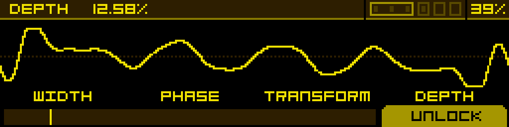
| Width | Phase | Transform | Depth |
| Reduces the width of the waveform without changing its pitch, by windowing it between blank spaces. It will affect the harmonics of the wave. | Changes the starting point of the waveform. When using Width, it scrolls which segment of the wave is heard. | Selects one of 38 wave-altering effects, organised in three families: spectral (SP:), algorithmic (AL:) and phase distortion (PD:*). See the table below. | Controls the strength of the selected Transform. Disabled while Transform is Off. |
Wavetable Transform reference
| Family | Transforms |
Spectral (SP:*) | SP:Smear · SP:Stretch · SP:Shift · SP:Noise · SP:Fold · SP:Crush · SP:Odd · SP:Comb · SP:Mirror · SP:Gate · SP:Rev · SP:Void · SP:Quant · SP:Ring · SP:Exp · SP:Freze · SP:OctFd · SP:Decim · SP:Dble · SP:Prime · SP:SubH |
Algorithmic (AL:*) | AL:Folder · AL:Decimtr · AL:Fade |
Phase distortion (PD:*) | PD:Sync · PD:SyncWin · PD:Asymm · PD:Sine · PD:Triang · PD:Fractal · PD:Bounce · PD:Gravity · PD:Tidal · PD:Magntic · PD:Crystal · PD:Steps · PD:Quantum · PD:Collaps |
Saw model
A saw wave with virtual sync capabilities. The Saw model has 2 pages. Page 1 is the same as mentioned earlier.
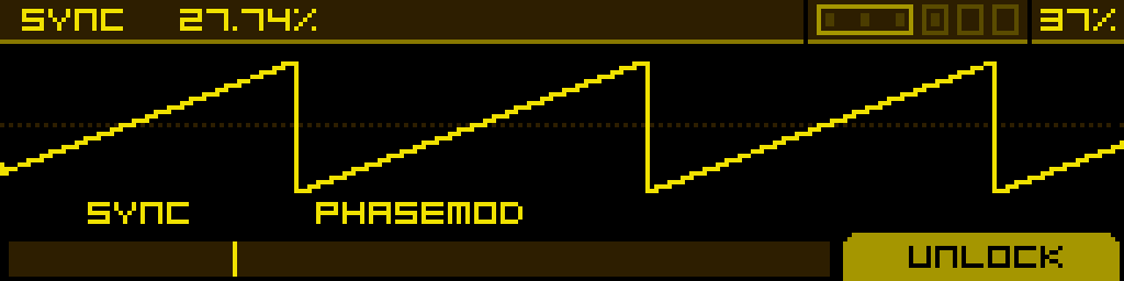
Page 2
| Sync | PhaseMod | ||
| Above 0%, the saw wave is synced to a master oscillator. This adjusts the frequency of the slave oscillator you're hearing. Modulate for classic sync sounds. | Above 0%, the saw wave's phase is modulated by another oscillator tuned at 0.75 times the frequency of the Saw. Increasing the parameter augments the modulation depth. |
SuperSaw model
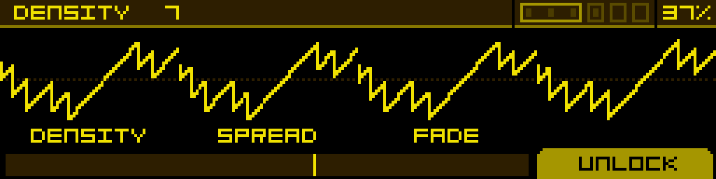
A swarm of detuned saw waves. The SuperSaw model has 2 pages. Page 1 is the same as mentioned earlier.
Page 2
| Density | Spread | Fade | |
| Choose the number of saw waves in the swarm, up to 12. | Adjust the amount of detuning between the waves. | Apply a volume fade on the most detuned saw waves to make the output less chaotic. |
Square model
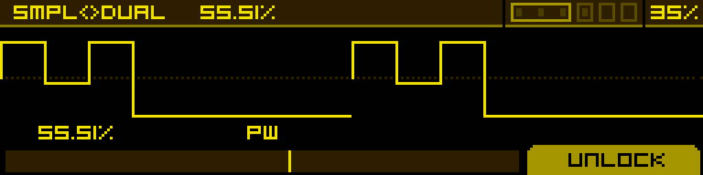
A Square wave with PWM capabilities. The Square model has 2 pages. Page 1 is the same as mentioned earlier.
Page 2
| Smpl<>Dual | PW | - | - |
| Add harmonics by dividing the positive part of the pulse in three pulse segments. | Adjust the pulse-width of the output wave. Modulate for classic PWM sounds. | - | - |
Fold model
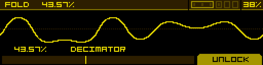
A sine wave folded using the Chebyshev method. The Fold model has 2 pages. Page 1 is the same as mentioned earlier.
Page 2
| Fold | Decimator | ||
| Increase the number of folds in the wave to add harmonics. | Reduces the bit rate to add harmonics. |
Fold2 model
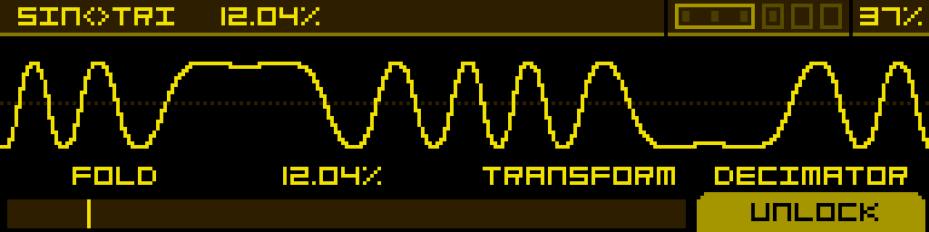
Two different out-of-phase waves are folded using the sinusoidal fold method. The Fold2 model has 2 pages. Page 1 is the same as mentioned earlier.
Page 2
| Fold | Sin<>Tri | Transform | Decimator |
| Increase the number of folds in the wave to add harmonics. | Crossfade between a sine and a triangle wave, which are out-of-phase with each other. | Adjust the phase of the sine and skew the triangle. | Reduces the bit rate to add harmonics. |
FM 2Op model
A lightweight 2-operator FM engine: a single sine modulator (OP2) drives a fully-featured carrier (OP1). The carrier reuses the same DSP as the FM1–FM8 operators, so it inherits the same 11 type families and per-operator waveform shaping — but with no routing matrix and no second carrier, this model costs roughly a third of the CPU of the 4-op FM models. Use it when you want a simple FM timbre without paying the full FM-engine bill.
The FM 2Op model has 2 pages. Page 1 is the same as mentioned earlier.
Page 2
| Type | Wave | Ratio | Depth |
| Synthesis flavour of the carrier (OP1). Same 11 types as the 4-op engine: Linear, Lin PD, Lin WF, OPS, OPN2, OPM, OPN, OPZ, OPLL, Noise, Exp PD. | Carrier waveform / phase-modulation shape. Behaviour depends on the selected Type — picks one of 16 waveforms on Linear types, or sets a phase-modulation amount on the YM-style chip types. | Frequency of the modulator (OP2) expressed as a multiple of the carrier frequency. Stepped by 0.25 by default. | Modulation depth — how strongly OP2 modulates OP1. The classic FM timbre control. |
A Feedback parameter is also exposed on this page (carrier self-feedback) — at high settings it pushes the sine carrier towards sawtooth-like or noisy spectra, just like the per-operator Feedback on the 4-op engine.
Ratio is stepped by 0.25 by default. Hold the button below the Ratio parameter and turn the Stepped parameter off in the SETTINGS tab to free it up.
VOSIM model
A vocal-style oscillator inspired by the VOSIM technique developed at the Institute of Sonology in Utrecht in the 1970s. Two hard-synced formant peaks are multiplied by a carrier envelope so the oscillator produces formant-filtered, vowel-like timbres without ever leaving the oscillator stage — no external filter required.
The VOSIM model has 2 pages. Page 1 is the same as mentioned earlier.
Page 2
| F1 | F2 | Shape | |
| First formant frequency, 50 → 5000 Hz (default 700 Hz). Sets the lower vocal peak. | Second formant frequency, 50 → 5000 Hz (default 1100 Hz). Sets the upper vocal peak. Combined with F1, the F1/F2 pair sweeps through the classic vowel space. | Carrier-envelope reset phase, 0 → 100 % (default 50 %). Reshapes the windowing applied to the formant pair — at low values the spectrum is brighter and more nasal, at high values softer and more rounded. |
Tip: VOSIM speaks the language of vowels. Modulate F1 and F2 with two slow, offset LFOs to morph between A / E / I / O / U over time, or assign them to a Macro for a single "vowel" knob.
FM1 to FM8 model
A 4-operator FM engine with 8 routing topologies (FM1–FM8). Each operator can be configured independently — its synthesis type, waveform shape, ratio, modulation depth and feedback are all per-operator. Output A is the carrier (operator 1) signal; output B is a side mix from a sibling operator. The Mix knob blends between the two.
The FM models have 6 pages. Page 1 is the same as mentioned earlier. Pages 2–6 below are dedicated to FM editing.
Page 2 — Type
| OP4:Type | OP3:Type | OP2:Type | OP1:Type |
| Selects the synthesis flavour of each operator. 11 types available, identical for every operator: Linear, Lin PD, Lin WF, OPS, OPN2, OPM, OPN, OPZ, OPLL, Noise, Exp PD. Six of these (OPS, OPN2, OPM, OPN, OPZ, OPLL) reproduce the response of period-accurate FM chips from the 1983–1988 era. | |||
Page 3 — Wave
| OP4:Wave | OP3:Wave | OP2:Wave | OP1:Wave |
| Per-operator waveform shaping. The exact effect depends on the operator's Type — typically a phase-distortion / waveform-select control that morphs the operator's output between sine variants. | |||
Page 4 — Ratio
| OP4:Ratio | OP3:Ratio | OP2:Ratio | OP1:Ratio |
| Frequency of each operator, expressed in multiples of the carrier frequency. Stepped by 0.25 by default. | |||
Ratio parameters are stepped by 0.25 by default for ease of use, but this can be freed: hold the button below the ratio parameter of the desired operator, then go to the "SETTINGS" tab and turn the "Stepped" parameter off.
Page 5 — Depth
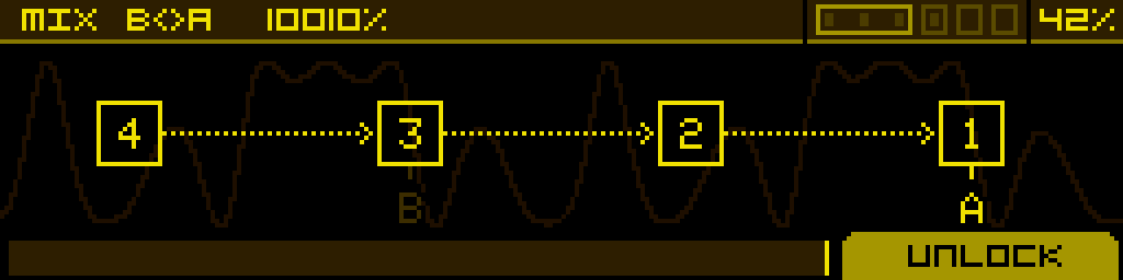
| OP4:Depth | OP3:Depth | OP2:Depth | Mix B<>A |
| Amount at which OP4 modulates the target operator(s) defined by the algorithm. | Amount at which OP3 modulates the target operator(s). | Amount at which OP2 modulates the target operator(s). | Mix between outputs A and B. At 50% both outputs are equally summed. |
Page 6 — Feedback
| OP4:FB | OP3:FB | OP2:FB | OP1:FB |
| Per-operator feedback amount. Each operator can feed its own output back into its phase input — at high settings this turns sines into noisy / sawtooth-like spectra. | |||
RingMod model
Two ring-modulation algorithms where one oscillator's frequency is a multiple of the other one. Algorithm A is a saturated ring modulation; algorithm B is more like a diode-based ring modulation. The RingMod model has 2 pages. Page 1 is the same as mentioned earlier.
Page 2
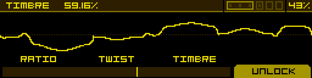
| Ratio | Twist | Timbre | |
| Selects the modulator frequency, as a multiple of the carrier frequency. | Distort the phase of the modulator oscillator. | Morph from algorithm A to algorithm B. |
CZ model
A phase-modulation and wave-windowing algorithm inspired by the Casio CZ series. The CZ model has 2 pages. Page 1 is the same as mentioned earlier.
8 waveforms are available and can be combined: Saw, Square, Pulse, DblSine, SawPulse, Reso1, Reso2, Reso3.
Page 2
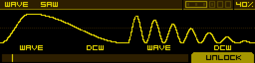
| Wave | DCW | Wave | DCW |
| Select a target wave. If the second Wave parameter is not Off, this one selects a target wave for every odd cycle of the main sine. | Simulates a filter sweep by using a different phase modulation on each wave (combined with windowing on the Reso1, Reso2 and Reso3 waves). At 0% only the main sine is heard, and at 100% only the target wave is heard. | Selects a target wave for every even cycle of the main sine. | Same as the first DCW, but applied to the second Wave selector. |
Noise model
A filtered noise with sample & hold. The Noise model has 2 pages. Page 1 is the same as mentioned earlier.
Page 2
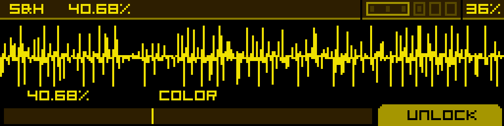
| S&H | Color | ||
| Amount of time the noise sample is held before refreshing. | To the left: low-pass cutoff from 0% to 100%. To the right: high-pass cutoff from 0% to 100%. |
Chip model
A vintage chip-tune oscillator that emulates the response of 6 historical sound chips. The Chip model has 2 pages. Page 1 is the same as mentioned earlier.
Page 2
| Chip | Param 1 | Param 2 | Param 3 |
| Selects the chip family. 6 choices: 2A03 (NES), DMG (Game Boy), SID6581 (Commodore 64), TIA (Atari 2600), SN76489 (Sega), WSG (Namco arcade). | Chip-specific parameter, mapping varies per chip. | Chip-specific parameter, mapping varies per chip. | Chip-specific parameter, mapping varies per chip. |
FLT ENV / AMP ENV tabs
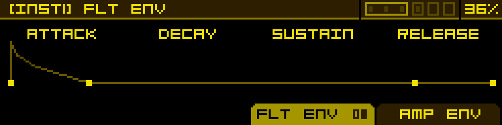
The Synthesizer has two built-in ADSR envelopes — one feeding the Filter stage (FLT ENV) and one feeding the Amp stage (AMP ENV). They are accessed as alternate tabs:
- Press ALT + FILTER tab to open the FLT ENV tab.
- Press ALT + AMP tab to open the AMP ENV tab.
Each envelope has the standard A / D / S / R parameters plus per-stage curve shaping (CurveA, CurveD, CurveR). Both envelopes are exposed as modulation sources (ADSR AMP, ADSR FLT) and can be assigned to any modulatable parameter.
By default these envelopes are pre-wired as regular modulations in the MOD 1 slot of two parameters:
- ADSR AMP is assigned to DCA2 → MOD 1, so notes have an envelope.
- ADSR FLT is assigned to Filter 1 cutoff → MOD 1, so the filter opens with the envelope.
These default assignments behave exactly like any modulation you would create yourself: long-press the button below DCA2 or Filter 1 cutoff to open MOD ASSIGN, where you can adjust the Attnv of MOD 1, remove the envelope (set MOD 1 to Off), or replace it with another source. The envelope itself remains available in the MACHINE category of MOD ASSIGN, so you can re-assign ADSR AMP or ADSR FLT to any other parameter (or back) at any time.